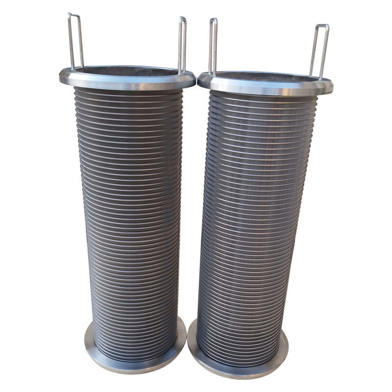
Johnson screen / V-wire screen / slot tube — slot 0.025 mm to 10 mm
Description · Material · Specifications · Applications
1. Product Description
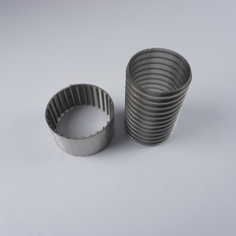
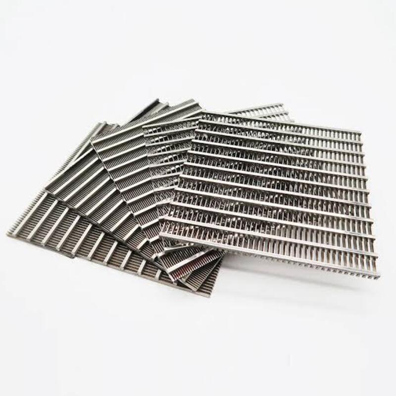
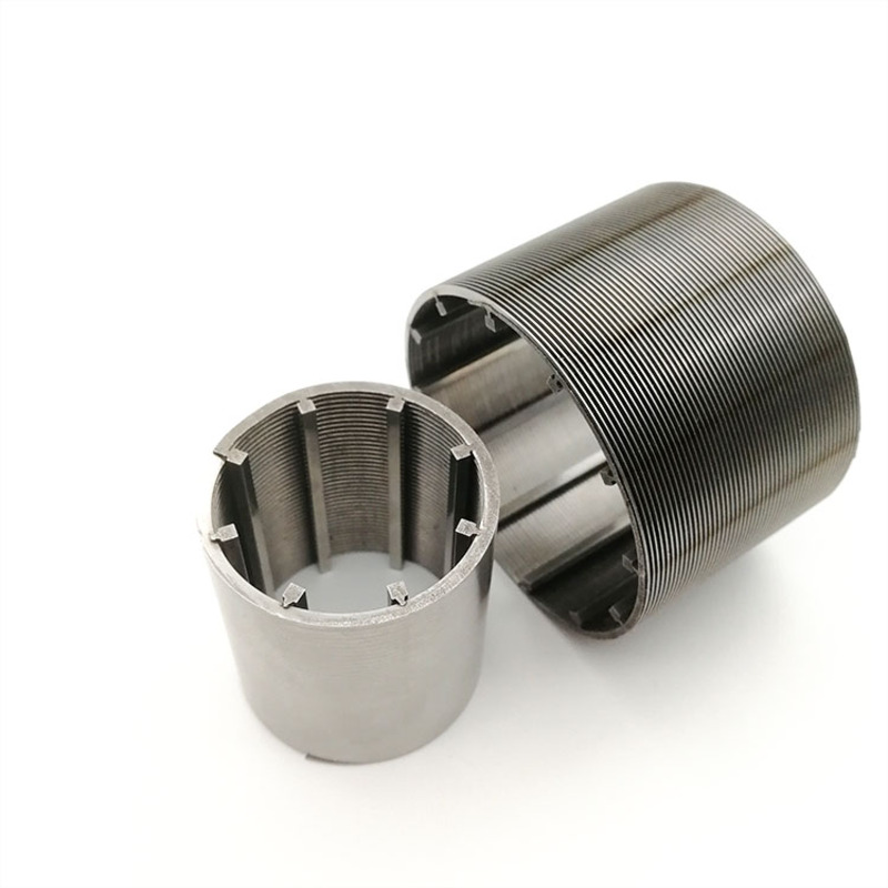
Wedge wire screen — also known as Johnson screen, V-wire screen, profile wire screen, wire wrapped screen or slot tube — is manufactured by winding a V-shaped (wedge) profile wire around longitudinal support rods and resistance-welding the two together at every intersection on a fully automated machine. The result is a continuous-slot screen with a smooth outer surface and an exceptionally rigid, gap-free welded structure.
The defining feature is the triangular cross-section of the profile wire. The slot between two adjacent wires is narrowest at the working surface and widens progressively inwards, so particles that reach the slot are not wedged in place: they either pass through or are easily flushed away. This self-cleaning geometry is why wedge wire screens keep their flow capacity where woven mesh or perforated plate would blind over.
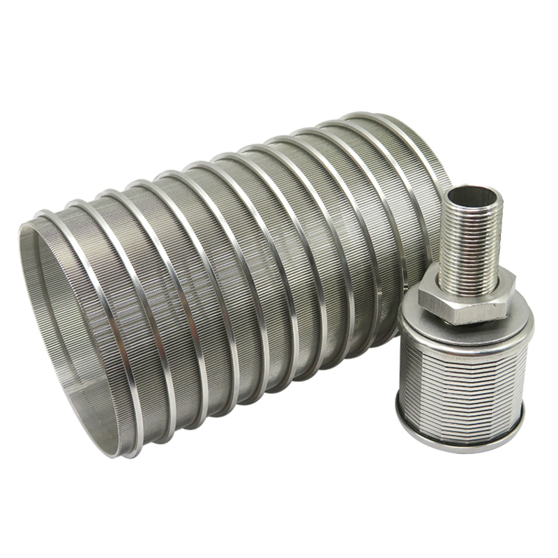
Wedge wire screen is also made in the reverse orientation, and the profile wire and support rods are produced in-house by rolling round wire through a series of rolling and annealing operations. Bolin supplies wedge wire screens in panel, sheet, tube and cylinder form, together with the profile wire and support rod used to build them.
This document covers the finished screen. The profile wire and support rod from which it is built are described in the companion document, “Wedge Wire — Product Introduction”.
2. Product Types
| Type |
Form |
Typical duty |
| Wedge wire screen panel / sheet |
Flat welded panel or sheet |
Intake screens, vibrating and dewatering screens, filter floors, support grids, brewery mash tun false bottoms. |
| Wedge wire slot tube / cylinder |
Cylindrical slotted tube |
Water wells, oil and gas production and sand control, centrifuge baskets, water distribution headers, resin traps. |
| Sieve bend (curved screen) |
Arc profile panel |
Starch and sugar dewatering, coal and mineral classification, wastewater DSM screens. |
| Filter element / nozzle |
Cartridge, candle or nozzle body |
Self-cleaning filter elements, sand filter tank nozzles, vessel lateral assemblies, process liquid filtration. |
3. Material Composition
Wedge wire screens are resistance-welded, so the screen is made from the same alloy throughout — profile wire and support rod in a matching grade. Austenitic stainless steel is the standard choice; molybdenum-bearing and duplex grades are selected for chloride, acid and high-strength duty.
| Grade |
UNS |
C max. |
Cr |
Ni |
Mo |
Others |
| SS304 / SUS304 |
S30400 |
0.07 |
18.0–20.0 |
8.0–10.5 |
— |
Fe balance |
| SS304L / SUS304L |
S30403 |
0.030 |
18.0–20.0 |
8.0–12.0 |
— |
Fe balance |
| SS316 / SUS316 |
S31600 |
0.08 |
16.0–18.0 |
10.0–14.0 |
2.00–3.00 |
Fe balance |
| SS316L / SUS316L |
S31603 |
0.030 |
16.0–18.0 |
10.0–14.0 |
2.00–3.00 |
Fe balance |
| SS321 / SUS321 |
S32100 |
0.08 |
17.0–19.0 |
9.0–12.0 |
— |
Ti ≥ 5 × C |
| Duplex 2205 |
S32205 |
0.030 |
22.0–23.0 |
4.5–6.5 |
3.0–3.5 |
N 0.14–0.20 |
| Super duplex 2507 |
S32750 |
0.030 |
24.0–26.0 |
6.0–8.0 |
3.0–5.0 |
N 0.24–0.32 |
Typical ranges per ASTM A240 / EN 10088-2; balance iron and residual elements (Mn, Si, P, S, N) are not shown. Other materials — stainless steel 310S, titanium, Monel, Hastelloy, Inconel and low-carbon galvanised or coated steel — are available on request. Wire is supplied to ASTM A580/A580M, so mechanical values can differ from the sheet data quoted above.
4. Physical and Mechanical Properties
| Property |
SS304 / 304L |
SS316 / 316L |
Remarks |
| Density (g/cm³) |
7.93 |
7.98 |
At 20 °C |
| Melting range (°C) |
1398–1454 |
1375–1400 |
Solidus to liquidus |
| Modulus of elasticity (GPa) |
193 |
193 |
At 20 °C |
| Thermal conductivity W/(m·K) |
16.2 |
16.3 |
At 100 °C |
| Thermal expansion µm/(m·K) |
17.3 |
16.0 |
Mean 0–100 °C |
| Electrical resistivity (µΩ·m) |
0.72 |
0.75 |
At 20 °C |
| Hardness, annealed |
≤ 92 HRB |
≤ 95 HRB |
ASTM A240 |
| Tensile strength, min. (MPa) |
515 |
485 |
ASTM A240 |
| Yield strength Rp0.2, min. (MPa) |
205 |
170 |
ASTM A240 |
| Elongation, min. (%) |
40 |
40 |
ASTM A240 |
Screen performance parameters
| Parameter |
Value / range |
Notes |
| Slot width (filtration rating) |
0.025 mm – 10 mm |
Produced in 0.025 mm increments; wider slots on request. Equivalent to 25 – 10 000 µm. |
| Slot tolerance |
± 0.05 mm to ± 0.10 mm |
Per the ISO-based slot tolerance table in section 7.2; tighter tolerance available on request. |
| Open area |
15 % – 65 % |
Set by the slot-to-wire-width ratio; typically 60 % in well screen constructions. |
| Profile wire width |
0.75 – 3.0 mm |
Standard production sizes in the companion wedge wire document. |
| Profile wire height |
1.35 – 6.0 mm |
Height sets the slot depth and the wire stiffness. |
| Support rod |
2.0 × 3.0 mm to 5.0 × 8.0 mm |
Round bar Ø 5–12 mm and flat bar also available. |
| Cylinder / tube outside diameter |
25 – 1000 mm |
Reference range; fabricated sections larger on request. |
| Maximum panel / tube length |
up to 6000 mm |
Longer lengths can be supplied as welded sections. |
5. Key Characteristics
- Self-cleaning V-shaped slots — the slot widens inwards, so particles are not wedged in place and blinding is minimised.
- High open area — typically 15–65 %, well above perforated plate (roughly 20–35 %) or woven mesh at a comparable rating, giving high throughput with a low pressure drop.
- Uniform, accurate slot width — consistent filtration and even liquid distribution across the whole screen surface.
- Very high strength and rigidity — the welded profile-wire and support-rod structure carries load in both directions and resists abrasion, deformation and vibration.
- Automated spiral welding — a continuous, gap-free weld at every intersection, with no loose wires and no risk of wire movement in service.
- Easy to clean and backwash — the smooth outer working surface sheds filter cake readily and the screen tolerates repeated reverse-flow, chemical or high-pressure cleaning.
- Corrosion and heat resistance — available in 304, 316, 316L, 321, duplex 2205 and 2507, titanium and nickel alloys.
- Long service life at low maintenance cost — maximum process output with minimum downtime.
- Fully customisable — material, slot, profile wire, support rod, diameter, panel size, length, frame, edge treatment, end connections and flow direction are all made to order.
6. Construction and Slot Geometry
A wedge wire screen is defined by five parameters: the profile wire used as the working surface, the support rod, the support rod spacing (pitch), the slot width, and the flow direction. Open area and weight follow directly from the first four.
Open area
Open area is the ratio of slot surface to total screen surface:
OA (%) = S / (S + W) × 100
where S = slot width and W = width of the working profile wire, both in the same unit. Because the profile wire flares towards its base, the true hydraulic opening is larger than the surface calculation suggests.
Screen weight
Screen weight = profile wire weight + support rod weight. The two contributions are calculated separately from the wire cross-section, the pitch and the support rod spacing, which is why a screen with the same slot can be quoted in several wall thicknesses and weights.
Flow direction
| Orientation |
Working surface |
Where it is used |
| FOTI — filtration from outside to inside |
Outside. The profile wires are welded with the wedge (point) towards the inner support rods, leaving the outer face smooth and unobstructed. |
The most common design. Used for well screens, intake screens, candle elements and most liquid filtration. |
| FITO — filtration from inside to outside |
Inside. The profile wires are welded with the flat top towards the inner support rods. |
Used where the filtrate leaves from the inside, for example in some pressure screens and vessel internals; the internal working surface is interrupted by the support rods. |
7. Standard Specifications
7.1 General specification
| Parameter |
Specification |
| Other names |
V-wire screen / Johnson screen / profile wire screen / wire wrapped screen / slot tube / continuous slot screen |
| Materials |
SS304 / 304L / 316 / 316L / 321 / duplex 2205 / super duplex 2507 / titanium / Monel / Hastelloy / Inconel |
| Slot width |
0.025 mm (25 µm) up to 10 mm; larger slots available on request |
| Slot increments |
0.025 mm |
| Slot type |
Continuous slot, self-cleaning, non-clogging |
| Open area |
15 % – 65 % |
| Product forms |
Welded panel / sheet; slot tube / cylinder; sieve bend; filter element, nozzle and lateral assembly; profile wire and support rod |
| Cylinder outside diameter |
25 – 1000 mm (reference) |
| Maximum length |
up to 6000 mm |
| Slot tolerance |
± 0.05 mm to ± 0.10 mm (see 7.2) |
| End connections |
Plain ends, threaded (BSPT / NPT / FNPT), flanged, welded ring, or to customer drawing |
| Surface finish |
Pickled and passivated, bright, or as welded |
7.2 Slot tolerance
| Slot size (mm) |
Tolerance band 1 (± mm) |
Tolerance band 2 (± mm) |
| 0.08 – 0.099 |
0.05 |
0.075 |
| 0.10 – 0.59 |
0.05 |
0.10 |
| 0.60 and above |
0.10 |
0.05 |
Slot tolerance is controlled against the ISO-based slot tolerance table used in our quality management system; two tolerance bands apply depending on how the production run is classified. Acceptance criteria, and tighter tolerances where the application requires them, are agreed at the time of order.
7.3 Water well screen — technical data
Typical wire-wrapped well screen sizes, with the screen weight, the maximum installation depth and the tensile strength of the screen body:
| Outside dia. (mm) |
Inside dia. (mm) |
Screen weight (kg/m) |
Max. depth (m) |
Tensile strength (lbs) |
| 43.18 |
27.94 |
2.67 |
304.8 |
4,200 |
| 63.50 |
50.54 |
2.82 |
304.8 |
2,000 |
| 66.04 |
50.80 |
3.27 |
304.8 |
3,400 |
| 76.20 |
60.96 |
3.86 |
304.8 |
4,200 |
| 91.44 |
73.66 |
4.31 |
304.8 |
4,200 |
| 93.98 |
78.74 |
4.46 |
304.8 |
4,200 |
| 116.84 |
101.60 |
5.50 |
182.88 |
4,800 |
| 119.38 |
104.14 |
5.65 |
182.88 |
4,800 |
| 142.24 |
127.00 |
6.69 |
121.92 |
5,600 |
Values are typical for standard construction and are given for reference; they vary with slot width, profile wire, support rod and wall thickness. Confirm against the actual construction before using them for a completion design.
8. Available Product Forms
| Product |
Description |
| Slot tube / screen cylinder |
Wire-wrapped cylindrical screen with plain, threaded or flanged ends; the base product for wells, filters and distribution headers. |
| Flat panel / sheet screen |
Welded flat screen, or a slot tube opened and flattened. Supplied with or without a frame, with optional rubber or polyurethane edge. |
| Sieve bend / curved screen |
Arc-profile panel for dewatering and classification; standard arc sizes 585 × 1600, 710 × 1600 and 825 × 1600 mm, with radius and open area to order. |
| Centrifuge basket |
Tapered or cylindrical basket screen for decanter and pusher centrifuges. |
| Rotary drum screen / pressure screen drum |
Drum and pressure-screen cylinders for pulp and paper, municipal and industrial wastewater. |
| Screw press screen cylinder |
Slotted cylinder for screw press dewatering of sludge, manure and food waste. |
| Intake screen |
Cylindrical or panel intake screen for surface water, cooling water and desalination intakes. |
| Filter nozzle |
Slotted nozzle body for sand filter tanks, ion exchangers and resin beds. |
| Vessel lateral assembly |
Header and lateral distribution assemblies for vessels and tanks. |
| Resin trap / support grid |
Retains ion-exchange resin and supports vessel internals. |
| Filter element / cartridge |
Slotted filter element or candle with threaded or welded end fittings; filtration rating 30–800 µm. |
Profile wire and support rod are supplied for screen manufacture and repair; they are detailed in the companion document, “Wedge Wire — Product Introduction”.
9. Typical Applications
| Industry |
Typical duty |
| Water and wastewater treatment |
Intake screens, water well screens and strainers, water distribution headers, sand filter nozzles, DSM and self-cleaning effluent screens. |
| Oil, gas and petrochemical |
Production and sand control screens, downhole screens, catalyst support grids, refinery process filtration. |
| Mining and coal |
Dewatering and classification screens, sieve bends, centrifuge baskets, coal washing and mineral sizing. |
| Food, beverage and brewing |
Mash tun false bottoms, starch and sugar dewatering, dairy and beverage filtration, grain and seed screening. |
| Pulp and paper |
Pressure screen cylinders, knotter and screen baskets, screw press dewatering, fibre recovery. |
| Pharmaceutical and chemical |
Process liquid and catalyst filtration, resin traps, vessel internals and distribution laterals. |
| Power generation |
Cooling water intake screens, condensate and process water filtration, demineraliser and resin support grids. |
| Agriculture and aquaculture |
Irrigation intake screens, slurry separation, feed and grain screening. |
10. Applicable Standards
| Scope |
Standard |
| Stainless steel wire (profile wire, support rod) |
ASTM A580/A580M — stainless steel wire |
| Stainless steel wire and rod |
ASTM A555/A555M — stainless steel wire and rod |
| Seamless stainless steel tube |
ASTM A269 — seamless and welded austenitic stainless steel tubing |
| Raw material composition |
ASTM A240 / EN 10088-2 — stainless steel plate, sheet and strip |
| Slot tolerance |
ISO-based slot tolerance table (see section 7.2) |
| Dimensional tolerances |
ISO 13920 — general tolerances for welded structures |
| Welded screen plate with strips |
JB/T 3278-2015 |
| Wire-wound stainless steel screen pipe |
SY/T 5182-2008 |
| Bends (sieve bends and fabricated elbows) |
JB/T 4265-1999 |
| Pressure screen for grain and oil machinery |
GB/T 26886-2011 |
| Sand control screens, downhole equipment |
ISO 17824:2009 (modified) — petroleum and natural gas industries, downhole equipment, sand screens |
| Pipe flanges and flanged fittings |
ASME B16.5-2017 |
11. Ordering Notes
- Please state the material grade, slot width, profile wire size, support rod size and pitch, product form, outside diameter or panel size, length, wall thickness, end connections and quantity.
- State the flow direction required — FOTI (outside to inside) or FITO (inside to outside) — and the particle size to be retained.
- For panels, please state the frame, edge treatment and whether a rubber or polyurethane edge is required.
- Slot width is normally specified in mm or micron; the conversion between units is direct (0.025 mm = 25 µm).
- Where three of the four principal parameters (slot width, profile wire width, open area and pitch) are known, the fourth can be calculated and confirmed before order placement.
- Mill test certificates to EN 10204 3.1, chemical assay, dimensional inspection reports, third-party inspection and pre-shipment sample approval can be arranged on request.