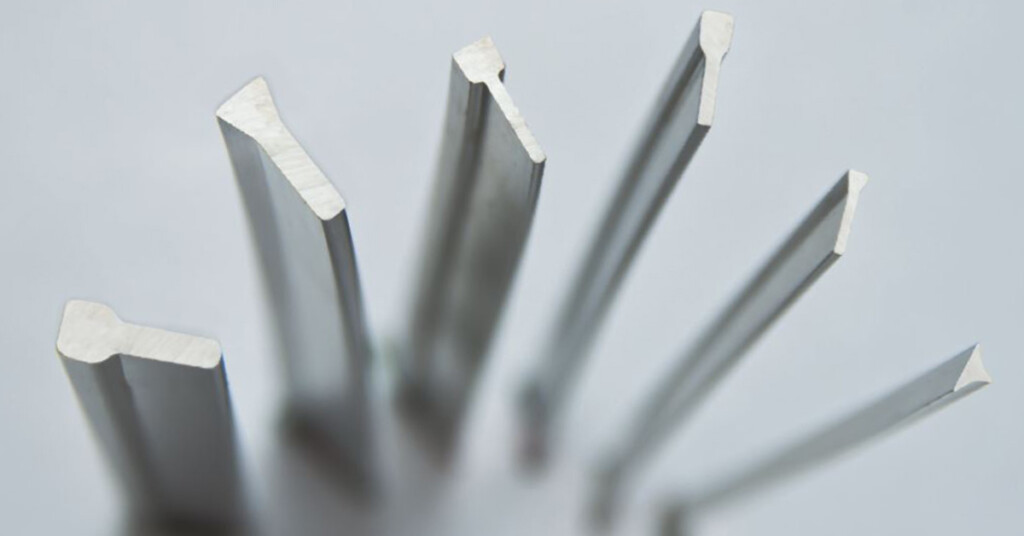
V-wire / profile wire / Johnson screen wire — width 0.75–3.0 mm, height 1.35–6.0 mm
Description · Material · Specifications · Applications
1. Product Description
Wedge wire is the profiled wire from which every wedge wire screen is built. It is produced by rolling round wire through a series of rolling and annealing operations until the section becomes a controlled triangle — a flat working face, two inclined flanks and a narrow base. The same process is used for the support rod that carries the wire. Both are rolled in-house, so the section, the alloy and the weld interface of the finished screen are fixed at source rather than bought in.
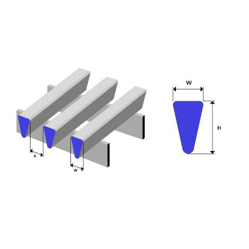
The triangular section is the functional heart of the product. When a V-wire is welded to a support rod with its point facing inwards, the gap between two adjacent wires is narrowest at the outer working surface and widens progressively towards the support rods. Particles that reach the slot therefore cannot wedge in place: they either pass through or are flushed away. This is the geometry behind the self-cleaning behaviour of wedge wire screens, and it is set by the wire, not by the screen that is subsequently assembled from it.
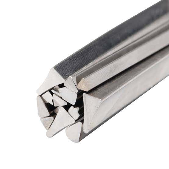
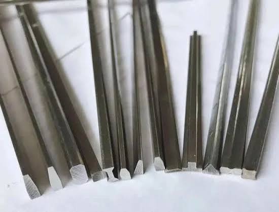
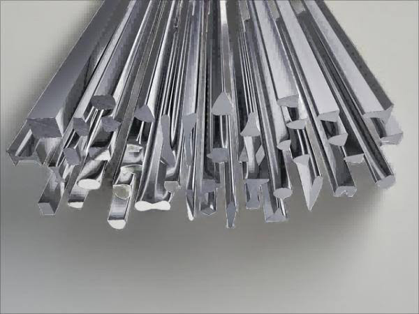
Wedge wire is supplied as continuous profile wire in coils or straight lengths, and as support rod in triangular, triangular-with-square-base, flat, notched or round section. It is used both as the winding wire and support rod for new screen manufacture and as replacement stock for the repair of screens already in service. Wire can be rolled in the reverse orientation as well, for screens that filter from inside to outside.
This document covers wedge wire — the profile wire and support rod — as a semi-finished product. The finished screens built from it (panels, slot tubes, sieve bends, baskets and filter elements) are described in the companion document, “Wedge Wire Screen — Product Introduction”.
2. Product Range
| Item |
Form |
Function |
| V-profile wire (wedge wire) |
Continuous rolled triangular wire, coils or straight lengths |
Working surface of every wedge wire screen; defines slot width and open area. |
| Support rod |
Triangular, triangular with square base, flat, notched, or round bar |
Runs perpendicular to the profile wire and holds the working surface at a constant pitch. |
| Reverse-orientation profile wire |
Triangular wire rolled for flat-top-to-support construction |
Working surface of FITO (inside-to-outside) screens. |
| Replacement wire and rod |
Cut lengths or coils in the original section |
Rebuilding or repairing existing screens without changing the filtration rating. |
3. Material Composition
Because the wire and the support rod are resistance-welded into one body, both are rolled in a matching grade. Austenitic stainless steel is the standard choice; molybdenum-bearing and duplex grades are selected for chloride, acid and high-strength duty.
| Grade |
UNS |
C max. |
Cr |
Ni |
Mo |
Others |
| SS304 / SUS304 |
S30400 |
0.07 |
18.0–20.0 |
8.0–10.5 |
— |
Fe balance |
| SS304L / SUS304L |
S30403 |
0.030 |
18.0–20.0 |
8.0–12.0 |
— |
Fe balance |
| SS316 / SUS316 |
S31600 |
0.08 |
16.0–18.0 |
10.0–14.0 |
2.00–3.00 |
Fe balance |
| SS316L / SUS316L |
S31603 |
0.030 |
16.0–18.0 |
10.0–14.0 |
2.00–3.00 |
Fe balance |
| SS321 / SUS321 |
S32100 |
0.08 |
17.0–19.0 |
9.0–12.0 |
— |
Ti ≥ 5 × C |
| Duplex 2205 |
S32205 |
0.030 |
22.0–23.0 |
4.5–6.5 |
3.0–3.5 |
N 0.14–0.20 |
| Super duplex 2507 |
S32750 |
0.030 |
24.0–26.0 |
6.0–8.0 |
3.0–5.0 |
N 0.24–0.32 |
Typical ranges per ASTM A240 / EN 10088-2; balance iron and residual elements (Mn, Si, P, S, N) are not shown. Other materials — stainless steel 310S, titanium, Monel, Hastelloy, Inconel and low-carbon galvanised or coated steel — are available on request. Wire is supplied to ASTM A580/A580M, so mechanical values can differ from the sheet data quoted above.
4. Physical and Mechanical Properties
| Property |
SS304 / 304L |
SS316 / 316L |
Remarks |
| Density (g/cm³) |
7.93 |
7.98 |
At 20 °C |
| Melting range (°C) |
1398–1454 |
1375–1400 |
Solidus to liquidus |
| Modulus of elasticity (GPa) |
193 |
193 |
At 20 °C |
| Thermal conductivity W/(m·K) |
16.2 |
16.3 |
At 100 °C |
| Thermal expansion µm/(m·K) |
17.3 |
16.0 |
Mean 0–100 °C |
| Electrical resistivity (µΩ·m) |
0.72 |
0.75 |
At 20 °C |
| Hardness, annealed |
≤ 92 HRB |
≤ 95 HRB |
ASTM A240 |
| Tensile strength, min. (MPa) |
515 |
485 |
ASTM A240 |
| Yield strength Rp0.2, min. (MPa) |
205 |
170 |
ASTM A240 |
| Elongation, min. (%) |
40 |
40 |
ASTM A240 |
Values are typical for the annealed condition and are quoted for reference; wire is supplied to ASTM A580/A580M and rod to ASTM A555/A555M, so certified mechanical properties follow the wire specification.
5. Key Characteristics
-
- Self-cleaning triangular section — the slot is narrowest at the working face and widens inwards, so particles are not wedged in place and blinding is minimised.
- Controlled width and height — the rolled section holds a consistent width, so slot width and open area stay uniform along the full length of the wire.
- High open area for a given slot — a narrow working face leaves more of the surface open than woven mesh or perforated plate at the same rating.
- Rigid section — the deep triangular profile resists bending, abrasion and vibration, and carries load through the welded assembly.
- Clean, repeatable weld interface — a flat base and controlled flank angle give a consistent resistance weld at every intersection.
- Rolled in-house from round wire — section, alloy and annealing condition are controlled at source, with no dependence on bought-in profile.
- Full alloy range — 304, 304L, 316, 316L, 321, duplex 2205, super duplex 2507, titanium and nickel alloys.
- Supplied as stock or to drawing — coils, straight lengths and cut pieces, in production sections or special profiles to order.
6. Dimensions and Tolerances
6.1 Surface profile wire (V-wire)
Profile wire is rolled from round wire through a series of rolling and annealing operations, giving a triangular cross-section with a controlled width and height. The standard production range is:
| Type |
Width (mm) |
Height (mm) |
Type |
Width (mm) |
Height (mm) |
| V-0.75 × 1.35 |
0.75 |
1.35 |
V-0.76 × 1.5 |
0.76 |
1.5 |
| V-1.0 × 2.0 |
1.0 |
2.0 |
V-1.2 × 2.3 |
1.2 |
2.3 |
| V-1.5 × 2.5 |
1.5 |
2.5 |
V-2.0 × 3.0 |
2.0 |
3.0 |
| V-2.0 × 4.0 |
2.0 |
4.0 |
V-2.5 × 4.0 |
2.5 |
4.0 |
| V-2.5 × 4.5 |
2.5 |
4.5 |
V-3.0 × 5.0 |
3.0 |
5.0 |
| V-3.0 × 6.0 |
3.0 |
6.0 |
|
|
|
Wider profile wire ranges, including 0.5 × 1.0, 1.8 × 2.7, 2.2 × 3.4, 2.5 × 3.6, 3.0 × 4.0 and 3.0 × 4.25 mm, are available to order.
6.2 Support rod
Support rods run perpendicular to the profile wire and hold the working surface at a constant pitch. They may be triangular, flat, notched or round; round bar and flat bar are used where greater stiffness or a different weld interface is needed.
| Section |
Width (mm) |
Height (mm) |
| Triangular |
2.0 |
3.0 |
| Triangular |
3.0 |
5.0 |
| Triangular |
3.0 |
6.0 |
| Triangular |
5.0 |
8.0 |
| Triangular with square base |
5.0 |
6.0 |
| Triangular with square base |
4.0 |
7.0 |
| Flat / notched bar |
2.0 |
3.0 |
| Round bar |
— |
Ø 5, 6, 7, 8, 9, 10, 12 |
6.3 Slot width, open area and tolerance
Slot width is created by the pitch at which the wire is wound, so the wire range sets the practical filtration range of the screen: 0.025 mm (25 µm) up to 10 mm, produced in 0.025 mm increments, with wider slots on request. Open area follows from the slot and the wire width:
OA (%) = S / (S + W) × 100
where S = slot width and W = width of the working profile wire, both in the same unit. Because the profile wire flares towards its base, the true hydraulic opening is larger than the surface calculation suggests. Typical open area is 15 % – 65 %, set by the slot-to-wire-width ratio.
| Slot size (mm) |
Tolerance band 1 (± mm) |
Tolerance band 2 (± mm) |
| 0.08 – 0.099 |
0.05 |
0.075 |
| 0.10 – 0.59 |
0.05 |
0.10 |
| 0.60 and above |
0.10 |
0.05 |
Slot tolerance is controlled against the ISO-based table used in our quality management system; two tolerance bands apply depending on how the production run is classified. Acceptance criteria, and tighter tolerances where the application requires them, are agreed at the time of order.
7. Applicable Standards
| Scope |
Standard |
| Stainless steel wire (profile wire) |
ASTM A580/A580M — stainless steel wire |
| Stainless steel wire and rod (support rod) |
ASTM A555/A555M — stainless steel wire and rod |
| Raw material composition |
ASTM A240 / EN 10088-2 — stainless steel plate, sheet and strip |
| Slot tolerance |
ISO-based slot tolerance table (section 6.3) |
| Dimensional tolerances |
ISO 13920 — general tolerances for welded structures |
8. Applications
Wedge wire is specified wherever a continuous, non-clogging slot has to survive abrasion, pressure or repeated backwashing. As a component it goes into:
| Industry |
Typical duty |
| Water and wastewater |
Water well screens, surface-water and cooling-water intake screens, strainers, distribution headers, sand filter nozzles. |
| Oil, gas and petrochemical |
Sand control and downhole screens, catalyst support grids, refinery process filtration. |
| Mining and coal |
Dewatering and classification panels, sieve bends, centrifuge baskets, coal washing. |
| Food, beverage and brewing |
Mash tun false bottoms, starch and sugar dewatering, dairy and beverage filtration. |
| Pulp and paper |
Pressure screen cylinders, knotter and screen baskets, fibre recovery. |
| Pharmaceutical and chemical |
Process liquid and catalyst filtration, resin traps, vessel internals. |
| Power generation |
Condensate and process water filtration, demineraliser and resin support grids. |
| Agriculture and aquaculture |
Irrigation intake screens, slurry separation, feed and grain screening. |
9. Ordering Notes
- State the material grade, the profile wire size (width × height) and the support rod section.
- State the slot width the wire will be wound to, or the pitch, so the open area can be confirmed before rolling.
- For stock supply, state coil or straight length, the total quantity, and whether cut-to-length pieces are required.
- State the flow direction of the screen being built — FOTI (outside to inside) or FITO (inside to outside) — as this sets the wire orientation.
- State the surface finish required: as rolled, pickled and passivated, or bright.
- Mill test certificates to EN 10204 3.1, chemical assay, dimensional inspection reports and third-party inspection can be arranged on request.